Sunday, July 7, 2013

The Brick Chronicles: Catalytic Converter/Exhaust Manifold (?) Phase III

A little over a month has passed since the last installment of the Brick Chronicles, which was semi-intentional. The brick has done about 2000 miles since, providing a legitimate testing period for assessing the state of the exhaust. Buttoning everything back up was trivial, so it wasn't post-worthy anyways. Time for Phase III: testing.

A few observations post-operation.

1) The "check engine" light has been on almost the entire time after the repair (I honestly can't remember when it first turned on, but it was within the first couple hundred miles). I suspected that the oxygen sensors were put in backwards, but that is not the case. I have noticed appreciable lag in the engine response, especially in situations like a 4th gear pull when trying to change lanes on the highway (i.e. low torque scenario). This is an entirely haptic observation but I've been driving this car long enough to notice these things. Most likely, the oxygen sensors needed replacing and/or were damaged in the installation process and are now mucking up the ECU reading; which would throw off the fuel injection mapping. 

2) In the last few hundred miles, the exhaust has gotten significantly louder, lower pitched, and sketchy-sounding in general. I think the clamp between the cat pipe and muffler pipe has been working itself loose over time. I bought some cherry loctite for the clamp hardware so that should be an easy fix. 

3) Most concerning of all, there is a clicking noise which is very clearly linked to engine RPM. While I was skeptical about there being an exhaust manifold leak, I think that a healthy dose of - not always smooth - highway driving has evinced the issue. This one will be harder to check, especially because I'd have to submit myself to carbon-monoxide poising to check it. Maybe I'll cave and let the shop diagnose this issue. This may also be contributing to observation 2. 

After addressing 2, I'll probably take it to the shop to avoid the dangerous fumes. It would be fun to do all the OBD II diagnostic stuff with an oscilloscope, but I don't have access to one currently (grad school soon!). Definitely making a good case for that pocket scope I've been procrastinating buying for forever.

But it's not all bad! After all, the brick has traveled another 2000 miles in sweltering heat and not broken down once. In other news, I was able to sell the old catalytic converter to the gentlemen at Davis Converters for a profit of $101. They won't reimburse you for shipping, but they sent a check for $128 and it was $27 to ship so that opens up some room in the budget to address the above issues. Interestingly enough, on a recent 900 mile trip I also monitored the fuel economy in both directions and the results were fairly consistent with what I used to get: 28.7 mpg there, 27.9 mpg back, versus about ~ 29 mpg in the past. The A/C was on full blast the entire time too so I was pleasantly surprised :)

Score:

D.E.C. catalytic converter - $396.55 (FREE SHIPPING!)
+        Exhaust flange gasket - $3.95
+     Oxygen Sensor Socket - $17.00
- Catalytic Converter Sold - $101.00
=                                         $315.50
($2000 - 315.50 = 1684.50)


Friday, May 24, 2013

The Brick Chronicles: Catalytic Converter/Exhaust Manifold (?) Phase II

Last time, in the Brick Chronicles, I had just ordered a catalytic converter. Since then, I've gotten to work on Phase II: Installation. With most people clearing out after graduation, I had a nice shady corner of the parking lot to myself. After all, I guess I am now a "shady tree mechanic."

Ad-hoc parking lot garage setup.
The jack setup in the picture above is rated at 9 tons (safety factor of about 6!). Anyways, the cat is split from the pipe that once connected it to the muffler, so the first step was to remove the section that was severed and not perturb the muffler pipe. The interface is this rusty two-piece bracket, which as far as I could tell was kept together by the remnants of some kind of pin. I pried the bracket apart using a flat head screw driver and some pliers. I honestly believe this is the procedure Volvo intended because if you're changing the cat then it follows that your hardware is ~15 years old.  

Rusty bracket.
Removing the brackets revealed the rusty pipe interface. I was a little concerned that this connection was welded at first. However, after blasting it with penetrating oil and torquing the free pipe with adjustable wrenches in opposite directions, it twisted right off. 

Rusty tubes.
Ta da.
Enter, the stubborn oxygen sensor.
With the pipe free, I could now access the downstream oxygen sensor. It makes most sense to remove the entire assembly before extracting the sensor because the pipe is free and unwieldy to secure. Before removing the pipe, a skid plate is blocking the sensor wire and must be removed.

Skidplate.
The wire is held to the frame via a series of clips which I pried up with a flat head screw driver. I did not have a good means of fixing the pipe in place in my parking space garage so I actually ended up following the wire up to the wiring harness in the engine bay, and removing the whole thing from the car. Remove the air distribution hose from the filter housing to access the wiring harness.

The silver washing machine hose like thing is the air distribution hose.
The left connection goes to the front sensor, and the right goes to the rear. There are red clips that you can pry up. At this point - poking around with a screwdriver in the engine bay - it would have been wise to start doing things one-handed because the chassis is live (floating ground). I elected to take off my watch and try not to touch things.

Oxygen sensor connectors.
One piece.
Moving on the oxygen sensor extraction, I'll start by saying how you shouldn't do this. I tried to take a shortcut and extract it while the wire was still tethered to the car; with the available slack, the assembly reaches just a few inches outside of the frame. I'm not proud of this, but my plan was to wedge one end of the pipe under my front tire and get a foot on the other end while wrenching on the sensor. Attempt one involved a liberal dose of penetrating oil (probably five coats all told) but was not enough to sufficiently break through the fillet of rust fusing the sensor to the pipe. No dice. For attempt two I lit a small fire (I hope nobody from DOTS reads this) and roasted the threaded part of the tube, attempting to expand it and release compressive stress on the threads. Still nothing. A third method involved melting candle wax into the threads to lubricate them. This failed because rust almost entirely concealed any access to the threads, and was admittedly only attempted because I read about this trick online and how cool would that have been if it worked? All of these attempts were useless because my method of constraining the pipe with tire and foot was JV at best.

Once I finally detethered the pipe/sensor assembly the sensor came right out with the help of a vice and a big wrench with a pipe to make it even bigger.

A more sensible strategy.
So, that's half of the cat removed and one oxygen sensor (of questionable functionality) salvaged. I am optimistic that the sensor still works and am reading into ways to diagnose this without a legit OBDII scanner (i.e. using an oscilloscope). We'll slate this as a problem for future self. Next up, I will remove the upstream oxygen sensor and the larger part of the cat, which is buried deep in the engine bay. Here's the updated scoreboard:

D.E.C. catalytic converter - $396.55 (FREE SHIPPING!)
+        Exhaust flange gasket - $3.95
+     Oxygen Sensor Socket - $17.00
=                                         $416.50
($2000 - 416.50 = 1583.50)

In the green for now at least. You can borrow oxygen sensor sockets from Autozone free but I figured this was an investment for future brick chronicles and car repair projects. Until next time.

Thursday, May 16, 2013

The Brick Chronicles: Catalytic Converter/Exhaust Manifold(?) - Phase I

I've had it.

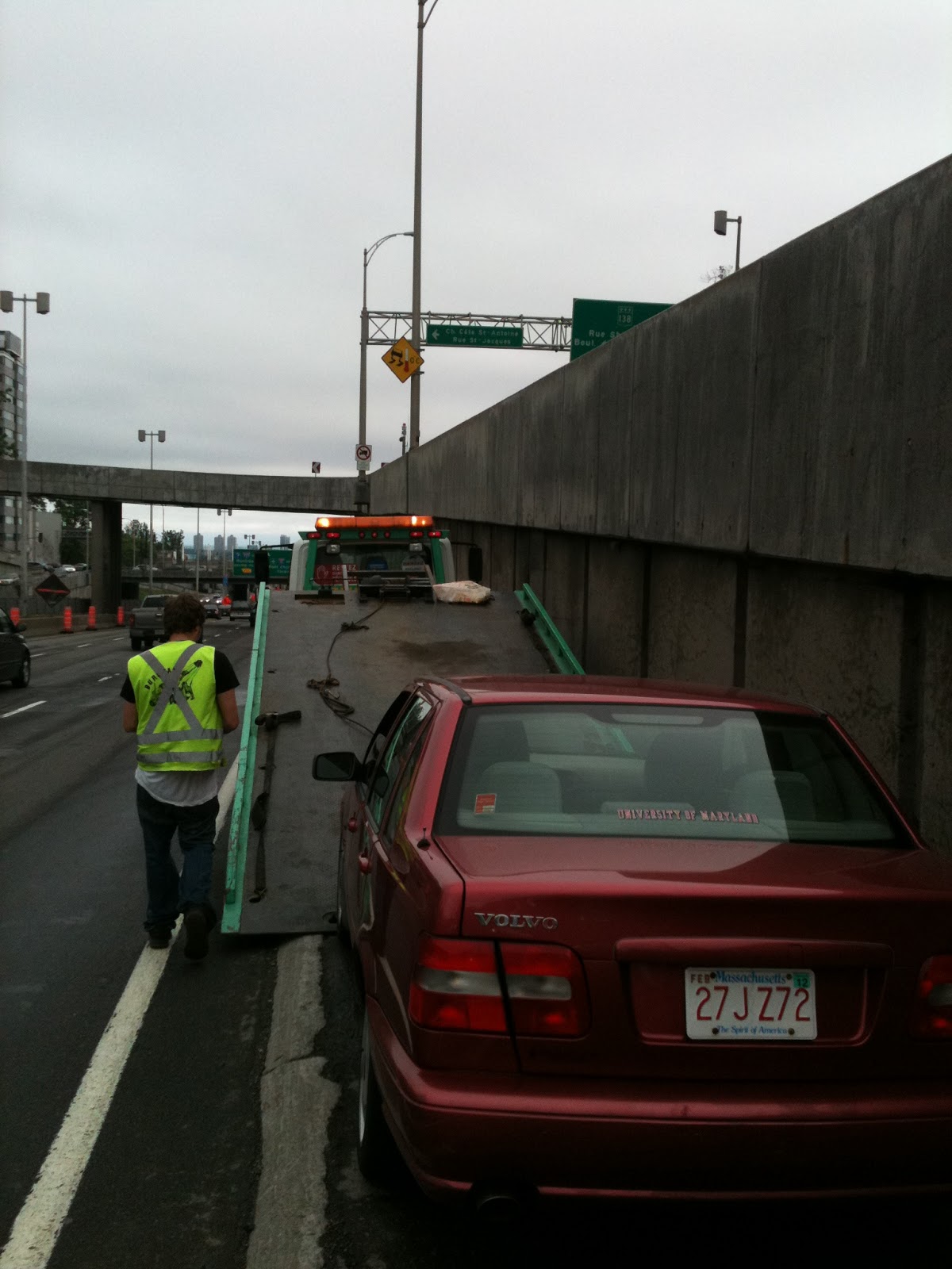
The other day I was driving in my '98 Volvo S70 when all of a sudden I heard this terrible noise resembling an old Civic with a cheap aftermarket exhaust kit. I panned left and right, initially thinking it was one of my road neighbors, until something bad happened: I changed gears only to hear this horrendous low-pitched babble following thine own engine RPM. Fortunately, I had only made it a few miles away from school when this all happened. The brick is a 15 year old car and according to the service history the exhaust hasn't been touched; it all made sense, I thought to myself as I poked around the car awaiting AAA. I had it towed to a garage near campus for $24 - cheap insurance in case my -- still driveable -- Volvo has something more serious it was hiding.

Old cat cantilevered off the exhaust manifold. 
The next morning, I awoke to a call from the garage owner who diagnosed both a failing exhaust manifold and catalytic converter, with an estimated price tag of $2,000 parts and labor. This far exceeded my premonition of a bad connection between the tailpipe and muffler. However, for those reading who know me (and my brick) you know that it takes a large number to startle me when it comes to car repair. This is the same car which had a timing belt tensioner fail in Canada, costing about $1,300 in towing and $3,000 to replace the engine. Other holes in my pocket include the time I went to prepare my car for a road trip and wound up with a $1,200 bill to replace A-arms and tie rods with worn ball joints and $400 for a radiator that one time. Fortunately, I have a habit of working year round and am able to fund my aging automotive sidekick.

Disaster strikes in Montreal.
This summer, though, I will be taking a rare break. For in the Fall I shall be blossoming into a beautiful graduate student butterfly, and heading the advice of every grad student I've ever talked to ever, I'm taking a damn break! I cannot remember the last summer like this (I think it must have been when I still went to summer camp) but it gave me an idea: now that I have the time, I can finally work on my car myself. That, combined with the realization that I now have a degree in mechanical engineering. I think this also certifies me to assemble IKEA furniture sans directions?

I guess this is a somewhat pedantic and anecdotal preface to the main point of this and future posts. This is that I'm sick of blindly paying garages to do work I can do myself -- putting on my DIY car repair hat. I picked up the car immediately after hearing the garage quote, had a loud, slow, and nerve-wracking drive back to campus, and then immediately began Phase I: Research. I scoured the internet for parts and such and found the Volvo original exhaust manifold (which I am still not convinced is busted) could be purchased for $431 or about $75 from a junkyard, and the catalytic converter for just $395 if I don't plan on driving to California anytime soon. With the latter not meeting California's strict emissions regulations, I could cut the cost of the part in half and then some. So at worst, I pay $1000+ and learn something, and at best $400+ and I still learn something. And in either scenario, I can't go to California. Seems reasonable, so I bought the cat, in addition to some small supporting hardware.

Strangest object to be delivered to the front desk. Probably the most chemically diverse as well.
Guess I'm not driving to Calif. any time soon.
This concludes Phase I. Let's review the score:

D.E.C. catalytic converter - $396.55 (FREE SHIPPING!)
+         Exhaust flange gasket - $3.95
=                                         $399.50
($2000 - 399.50 = 1600.50)

Off to a decent start! The next steps are to get the tools together and then do the actual work. Oh and graduation somewhere in between...but that's a completely different kettle of fish.

Monday, January 21, 2013

TOBL2: First Rolls

TOBL began as an idea that popped into my head one fateful night in the Fall of 2010 - sometime around here. Two years and a few months later, TOBL the sequel, is alive. Thinking about it this way, I'm not too far off Apple's new product release pace. In fact, TOBL original was controlled by my iPhone 3GS, where as now I have an iPhone 5. Interesting. Well, without further delay here's video of the first recorded rolls:
I cannot think of a more appropriate place for TOBL2 to be initiated than the filthy floors of the hallowed MITERS shop. After all, this is where the first TOBL was forged and where I learned most of the skills needed to create TOBLs. Okay, onto the technical part.

The numbers:

0.8 lbs
22 screws and bolts
6 wheels
2 bridges
7 different belts before getting just the right size
5mm of ground clearance
And my favorite: TOBL2 has traveled to and was worked on in 3 different states

To get to this point there were just a couple agonizingly simple loose ends to address. First was the belt and tensioning issue. Two posts (and four months!) ago, there's a picture of TOBL fully assembled and seemingly a few 1s and 0s away from action. However, the belts used in that picture were so tight they stalled the motors. Thing I learned: the pitch diameters given for FingerTech belts aren't precise enough to be designed around. I designed the whole pattern on the side plates to the millimeter to get the belt tension just right, but went through seven different belts and three different pulleys before hitting a winning combination.

Two: the radios. My brand new pair of xBees which I paired and updated the firmware on weren't talking to each other, I thought. Turns out I was using an older REV of my XPWMShield that was assembled incorrectly, denying power to the xBee on-board TOBL2. After fixing this and re-flashing the xBees to a wireless programming friendly bit rate of 57600, wireless communication was restored. I also learned a neat trick for wireless programming: when uploading the new code hit the Arduino reset button just after the program size pops up. There are fancier ways to achieve this automatically if you plan ahead a little with your circuit, but this works fine so long as you can get at the reset button! Wireless programming is a stupidly awesome upgrade for the TOBL line because otherwise there's no way to access the USB programming port.

After being shelved for months that was seriously all that needed doing...took me about 6 hours yesterday. With my volatile lifestyle and imminent graduation who knows how far I'll get on this list, but here's what I would like to happen next:

1. Clean up the wiring. A healthy application of zip-ties and more flexible wiring should take care of that. Needs more wall-flips.
2. Incorporate the servos that currently serve no function except a slight amount of structural integrity. They were intended to auto-tension or de-clutch the belts. This is mostly a mechanical task.
3. Develop the controller. My Python controller is quite rudimentary at the moment. I run the program in the shell, click on a little box, and then have the following discrete abilities: forward, reverse, left, right, and hard stop. The next step is to add speed control and a little calibration to account for unequal belt tension. A GUI would also be nice to trim different parameters.
4. IMU? Well, I am taking a controls lab this semester. Maybe I can use TOBL2 as the platform for some kind of controls problem like directional stabilization? The motors probably aren't fast enough to enable Segway-mode. Shame.
5. NEW ELECTRONICS. Bet I can take all the functionality of XPWMShield and MKI and put them onto one wireless motor controller board with a smaller footprint. It would also be nice to ditch the expensive Arduino Nano and just run straight off of an AVR chip with the Arduino bootloader. Regardless of whether this new batch of proprietary electronics makes it onto TOBL I'd like to have a more polished and convenient package to work with for whatever project comes next.

Time to go back to school.

Monday, October 29, 2012

Courtesy of Sandy

As I was sitting eating some yogurt on this rainy morning, I realized how much I miss working on my small robot friend TOBL2. Same story as always: school and my innate propensity to occupy my free time with responsibilities. Quick semi-relevant aside: I am loving being a TF this semester! The class just made the transition from the instruction-based part of the semester, to the build-and-test-an-autonomous-hovercraft portion. Already my inbox is being flooded with messages about batteries selection, which sensors to use, how to wire everything up, Arduinos (I know), etc.. In a way this class has curbed my appetite for making things, which is a nice side effect.

Anyhoo, I thought I'd share a video of TOBL2 in his current state. That is, a glorified python-enabled motor controller.


Not my finest cinematography but in the video you can see the directional keys have been mapped to forward, reverse, left, and right. There's a hard-stop function tied to the space bar as well (not shown). In this configuration, there's no speed control (I know booooo) but I will add two keys to increase and decrease speed. A lot of the controller specifics will be tweaked once I get the thing moving and can see what makes the most physical sense.

Speaking of assembling TOBL2, there are two factors impeding that from happening. The first is that no combination of the belts and pulleys I bought seem to work. Even with the nice auto-tensioning, one belt is just way too big and the other stalls the motors from being so tight. I am placing an order for some new smaller pulleys and couple different belt sizes. Selecting those was more scientific that I just made it sound, so hopefully I'll be able to drive this thing finally. The other road block is the wireless issues I've been having. Probably not a big deal, but I don't have much in the way of debugging those issues unless I go to my lab. I'll look into that once I get a working drivetrain.

Welp, thanks Hurricane Sandy for the little break from classes. Time to get caught up on everything else...

Tuesday, August 21, 2012

TOBL2: Press Pause

This past weekend my hard drive kicked the bucket. It's kinda my own damn fault. My external hard drive died a while ago, my computer started wheezing a bit in the Spring, and I didn't do anything about it. But I guess that's what you get for moving around all the time. Hopefully it can be recovered at some point, though it will probably be expensive.

Progress on TOBL2 is at a bit of a stand-still while I resolve computer issues (currently booting Ubuntu off a flash drive w/o a hard drive), finish up my summer internship, and transition from Colorado back to Maryland. But don't fret! It's really quite excruciatingly close to being done. Check it out:


Essentially needs code (old code is now gone :/)and some slight mechanical tweaking to get the tensioning spot on. Next time I'll take it apart and show off some of the cool machining I did last week.

It also turns out Maker Faire extended the Maker application deadline (shock) to this Friday, but it doesn't look like I'll be able to take advantage of that. More likely TOBL1 will be used as a placeholder get to get in the door. Can't do much about a hard drive dying so I'm proud of how far I got. I'll press play again after relocation.    

In the meantime debating updating computers a year earlier than anticipated...
 

Saturday, August 11, 2012

TOBL2: Build Week 2

Sitting down feels nice right now. This week was quite a push to keep TOBL2 on World Maker Faire schedule. If I'm honest, I don't think I'll be able to pull off a fully functioning bot for the August 17th deadline,  because I need to focus on my actually work work. A TOBL2 running the old iPhone controller or maybe a short autonomous program and no servo clutching is definitely still possible. So that's what I'll focus on. But I'm getting ahead of myself, here's where the bot's at after this week.


I tend to stay in the machine shop until the time I need to leave to make up for it coincides with the start of the afternoon mountain rain. Cold, but totally worth it. This week I machined all the mounting blocks which resolve the 90 degree angle between the drivetrain and electronics shelf. Remember the ridiculous custom stainless steel standoffs I made for TOBL1? I suppose these mounting blocks would be the machining analogue to those standoffs. Except machining really small things beats machining stainless any day. By a lot.

Here they are. The two on the left are for the battery tray and the four on the right support the electronics.


The only issue I can spot so far is the taper on the electronics plates from the water jet. The sides of these plates butt up against the motor plates and create a little gap. That's easy to fix.


The motor controller diodes also appear to be impeding one of the servos. That's another easy fix.


Oh yeah, and slightly more troubling issue: the belt appears to be undersized. I need to cut the motor shafts before attaching the outer plates and knowing for sure, but it's looking a bit tight when I just hack it together. The next size up belt has three more teeth so I'll probably invest in a set of those. Don't really need to worry about the slack thanks to the torsion spring tensioners.  

Still left to do (mechanically):

1. Add springs (coming in the mail Monday)
2. Shorten mounting blocks to make way for servo
3. Grind down electronics plates
4. Cut motor shafts, attach outer plates and see if belts too tight (if not skip 5)
5. Replace belts
6. Assemble 
7. Add servo linkage (probably won't worry about that 'til post-deadline)     

It's a bit ridiculous to go through every little mechanical task that needs doing, so ignore that if you like, it's really just a reference for me. This is definitely doable in 5 hour blocks of machining. I'd like to be done with this list by Tuesday, leaving the last three days to wire it back up, get decent code running, and capture the required media for the Maker application. This week we should finally see this thing move! Build week 3 engage.

P.S. Last weekend I moved for legitimately the 5th time this summer. So that's why there's a new backdrop for my pictures every week. I think this is my favorite so far. 

Saturday, August 4, 2012

TOBL2: Build Week 1

Enough waiting around. At the beginning of this week I received some of the last bits and pieces needed to finish TOBL2. Here's what I got:


The parts from the water jet turned out really nicely! Seeing these parts in isolation makes me realize what a bizarre hobby/design sense I have. But, I suppose the endless hours of SolidWorks dimensioning has paid off. The only slight hitch is that Big Blue Saw messed with the dwg file and forgot to include all of the outer plates - those should come in Monday.

Whilst I wait I've had the privilege of full access to an impressively well-equipped machine shop at work. They used to do production in-house so now there's just an overkill shop full of mills, lathes, a wire EDM, a water jet, and so forth. A MechE candy store, if you will. And the guys there are great. Direct quote: "Don't buy any more hardware or material, okay? We have anything you need."  This past week I've been scarfing down lunch and spending the rest of the break in the shop machining.

The first order of business was to clean up those inner plates.


With all those countersinks I tested the motor mounting assembly.


No interference! While playing with this something occurred to me: why the four letter words was I going to use tension springs to tension the belt? The thrust bearings are a perfect place to wrap torsion springs; which is a much cleaner solution. I guess you can't do all your design work in front of a screen.

But before getting too excited a little bit of math is in order. The Hitec HS-45HB feather servos are rated to provide maximum 1N of force for a 1cm arm (i.e. stall torque 1kg-cm). There is an arm on the motor mount too...about 1inch or 2.5cm where the servo will catch it. The motor is about 1.25cm from the point of rotation. On McMaster, the weakest spring that fits around a 5-40 screw is 0.64 in-lbf or 0.072 N-m. Then we do a simple moment balance:

ΣM = 0 = kθ + mgl - FL

θ = (FL-mgl)/k

If we make the safety factor 2, and assume the servo can only output 0.5 N, the spring will overcome the servo at about 1.2°. For safety factor 1 we can get up to 5.2° travel. Somewhere in that range should be enough lift to disengage the belt. If not, coils can be removed to decrease k. Here's a clearer picture of the plan (I realize this is already like plan C):


The next things that need doing are:

1. Clean up the outer plates when they come in
2. Press all the bearings
3. Machine the interfaces between the PCB shelf and inner plates
4. Servo linkage
5. Torsion springs
6. Assemble!

This is the plan for next week. In the background I'll be working on the new controller. I've been learning some python specially for the occasion and am hoping to be competent enough to write a controller that will use keyboard inputs (for now). Another new goal is to have TOBL2 operable enough to get video to submit for World Maker Faire New York. The submission deadline is in two weeks, on August 17th. Presumably I could always enter TOBL1 like last year and then bring TOBL2, but let's see if we can't do this honestly.

Saturday, July 21, 2012

TOBL2: Frame Design Complete!

About two minutes ago I placed my first Big Blue Saw order. This included all* of the missing pieces for TOBL2's frame which will be water jet cut from 1/8" 6061 aluminum plate. I guess one benefit to making everything so absurdly small is that I save some money on these sort of orders. Before shipping it came out to $81.40, which I hear is about the minimum you can pay. I like how Big Blue Saw gives you a preview of what your parts will look like if they were flying through a dessert.


Keeping this guy compact took a lot of changing dimensions, looking at the part in assembly, and then fine-tuning the dimensions further. The motors are mounted to a plate which can pivot, so that eats up a lot of space. The electronics stack also grew a little with the addition of the motor controller board. Altogether though, I'm very pleased with the way it turned out. The center of mass is going to be pretty atrocious, but I'm not ready to start selling TOBLs just yet, so that's alright.


I did away with the three aluminum posts mounted at each corner, and added two shelves. The top one is for the electronics stack (shown transparent) and the bottom one will hold the battery pack (ditto). PCBs should never be structural components, as I'm learning so well at work this summer. In this case, I had to be very creative, since the axles are now live and attaching posts to them won't work anymore. I prefer the old bulky aluminum posts mechanically, but I ordered an extra electronics shelf beam, so I can always put that above the servos if this doesn't cut it. As you can see, I had a little fun with the battery shelf.


Sexy battery tray


A lot of what took so long designing this frame was also anticipating what's going to go wrong. Having a drivetrain with triangular geometery, belts, springs, and moving motors, is really just asking for it - in terms of alignment issues. In an attempt to resolve all this, I put some redundant holes in to allow a little tuning upon assembly. For example, all those holes in the motor bracket are to adjust the spring tension (not easy to see in the picture below).

The drawing geometry and dimensions for these plates are disgustingly complex

 See what I mean? Gross

I also ordered some bearings on eBay, which had no picture, so that's always good. They were a dollar a piece though, so if they're the wrong size then I'm sure I'll create some crazy thing which will need them down the road. The asterisk in the second sentence is because as hard as I tried to make this the entire frame from the water jet order, I'm going to need to machine a few thicker (1/4") blocks at the interfaces of the plates and shelves. These are really straight forward, so hopefully the machinist where I work will be kind enough to let me knock those out some time.

Also, just bought a road bike...so that may have something to do with why TOBL had been moving so slowly recently...

Sunday, July 8, 2012

TOBL: Timers and PWM

Due to shear stubbornness I only brought one suitcase to Colorado. This means no soldering iron or useful tools. All I can do is SolidWorks and software. However, I've been doing a lot of CAD lately so I changed gears and took some time digging deeper into the inner workings of PWM signals. This is what I found:

Hardware, or timer-generated, PWM on AVR chips can be broken into two main categories. There is fast PWM and phase correct PWM. In fast PWM mode, the timer counts up from 0-255 (on 8-bit timers) and toggles the output once the compare register, OCRnx value, is reached. The output starts HIGH and switches LOW when this value is reached, meaning the higher the OCRnx value, the higher the duty cycle or time that the output is held HIGH. The graphs below represent the input sawtooth wave with two compare registers (most timers have two), an output PWM signal running 30% duty cycle, and one at 70% duty cycle, respectively.  
I wrote a MATLAB program to generate these waveforms; it will become more apparent why when explaining phase correct PWM.  
There is however a problem with fast PWM, for certain applications. The PWM signals above emulate the two outputs from a single timer. As can be seen above, the pulses start at the same time but at different duty cycles they do not stop synchronously. This is alright for controlling a single motor or dimming an LED, but for a pair of motors, this introduces error. Say for example there were a drivetrain with two motors, one left and one right (hmm kind of like TOBL). If TOBL were to steer left by running at 50% duty cycle on the left side and 100% on the right for x time, and repeat the other way around for the same amount of time, it would not end up at exactly it's original heading. In TOBL's case, with such a wide track and short wheelbase, this error is amplified. 

Ah hah! There is a solution to this issue called phase correct PWM. In this mode the timer counts from bottom to top and then top down to bottom again, toggling from HIGH to LOW crossing of the compare value on the way up, and from LOW to HIGH on the way down. This process looks like this:
There are a couple differences in these waveforms, starting with the triangle wave input. Because the timer has to count up and down the period of each duty cycle is doubled, or the frequency is halved, making it clear why fast PWM is named as such. You might also notice that now neither of the pulse edges align. However, more importantly, the pulses are centered around the top value. Returning to the two-motor vehicle example,  now using phase correct PWM, if the signal instruction were suddenly stopped, both motors would stop the same percentage of the way into their duty cycle. While this doesn't entirely eliminate the error, it is a lot better than fast PWM.  

On most timers fast PWM is the default and to change it you need to reset the timer/counter control register value to make the switch to phase correct. For the Arduino, which TOBL is based off, this looks like this:

TCCR2A = _BV(WGM20);


...for timer2. Of course there is a lot of other cool stuff to control at this level, so while doing this it may also be of interest to fiddle with the other registers. Setting the two outputs of the timer to non-inverting, the waveform mode to phase correct, and the prescale value to 256 would be this:

TCCR2A = _BV(COM2A1) | _BV(COM2B1) | _BV(WGM20);
TCCR2B = _BV(CS22);


The prescale value is useful because it adjusts the PWM frequency (for fast 8-bit, clock speed/prescale/255 = PWM frequency). So, while I may have cut the frequency in half by selecting phase correct mode, I can do the same to the prescale value to maintain the same PWM frequency. This is less important for motor control and more important for things like servos, which usually run at about 30-50Hz.

Anyways, the point of this tangent is that PWM can be a lot more complex than analogWrite(), and can be easily modified for any application. TOBL2 software now implements phase correct PWM, though I can't do much with it until I get a rolling chassis. If you're interested in the m.file that generated the graphs above, you can get it here. It's fun to play around with and see what's going on under the hood.

Tuesday, July 3, 2012

Blog Web Address Change: You Can't Ride a Fountain

I've changed the URL of my blog from lmh-tech.blogspot.com to ycraf.blogspot.com. When I started the blog a couple years ago I had a few naming ideas that didn't work out, but I wanted to start blogging so I just used "my initials - tech" as a placeholder until something more meaningful came along.

A little bit of history: Shane got me into Team 97 out of Cambridge, MA. We went to Nationals in Atlanta that year but when the competition was over we couldn't stop thinking of other things to build. At this point, the Edgerton Center Summer Engineering Workshop (I think that's the official title) was born. Our first project being this home-brewed segway.

In the process of selecting a project, Ed of the Edgerton Center had some ideas of his own. One which he was particularly adamant about was a fountain like one we saw in Atlanta. He wanted to equip it with sensors so you could run through and either not get wet at all, or get completely drenched. My response to which was "you can't ride a fountain." This went from an inside joke among the ECSEW team and developed into a personal philosophy. I see little point in creating things that don't move (sorry ardWINDo and gMeter) and you'll notice that DIY Segway, CapKart, BWD Scooter, and TinyKart are all things you can ride.

And so, about two years late, I give you: You Can't Ride a Fountain, a blog dedicated to building things that can be ridden and/or move.

Wednesday, June 27, 2012

TOBL2: Fire Day

Today we had what I'm going to call a fire day. It's just like a snow day, except with fire...never thought that was an option but that's what happened. Fortunately, where I work was closed due to smoke/air quality and not because there was nothing left of the place. Going outside wasn't the best option and we don't have a TV to watch Spain vs. Portugal in the EURO, so I spent the whole day playing with TOBL instead!

One thing  you don't realize when you relocate for a significant amount of time, is all the little things you're used to having access to. For example, usually when I do any design work I like having paper around to make sure what's in my head can actually be drawn and physically embodied. Well, I don't have any paper here, but we do have some old pizza boxes lying around...

Here was the original idea, of bringing the belt to the motor

And here would be some servo mechanism to tension the belt

What's this, moving the motor to the belt. Is this opposite day? No, it's fire day...

Now whenever somebody says to do envelope calculations, I'm going to do them on a pizza box, so much more room! Anyways, a few minutes into my brainstorming session I realized that my original plan of bringing the belt to a fixed motor was going to be difficult. Initially I wanted to do something like this:


The second spring isn't shown, but if it were the servo would have a neutral point where the spring displacements are equal and thus F1 = F2. This way, the servo could be floating during driving (tension) and the spring (F2) could do all the work. Then, when you need to detension, the servo arm would rotate downwards. However, this gets complicated when trying to load the pin that the tensioner bearings are riding on. This pin would require a slot on both of the plates that sandwich the wheels, and if the spring forces on either side weren't perfectly balanced the pin would tilt and not tension very well.

At this point, I thought back to my real first idea, which was to have the motor on a pivot. I threw out that idea originally because I didn't like having a motor that's not rigid with the frame (and I still don't). Practically though, this is a lot simpler because a motor itself does not rotate like a belt does -you can't bolt anything to a belt. So, that's where my third pizza box drawing comes in, which looks like this in SolidWorks form:

Most of the drivetrain complete 

Better shot of the motor mount plate

View of the drivetrain from the inside where the electronics will eventually sit

This of course had it's own challenges. The primary difficulty was making a robust mounting system for the motor that would withstand the torque from the belt tension on a single pin! To that end, the motor is centered as much as possible so that it's entire mass isn't cantilevered. The plate that carries the motor will serve as one washer of a thrust bearing, the other will be the inner plate, and a matching thrust bearing on the other side. Thrust bearings can take a lot of lateral load, these ones are rated to about 26lbs and were the only ones on McMaster small enough for the task. This picture should clarify what that actually looks like:


In the middle of the frame you can see the darker grey thrust bearings sandwiching the inner plate. To get everything to fit and not interfere (still not entirely done with that) took a lot of geometry and trial and error. Probably took more time to dimension this plate than design all of the electronics.

Not including the servo or supports to keep the inner and outer plates together. 

There are several advantages to this design. Firstly, due to the way the motors are mounted there is more room in the middle section for the electronics and battery to sit. I'm still playing with the tray that will mount all of that but I'm going to do my best to make TOBL2 narrower -this would make driving a lot more controlled. Unlike the original design, I don't have to worry as much about the springs. As you can see above on the shots of the drivetrain in its entirety, there are holes galore on the motor mounting plate, both to accept some sort of turnbuckle from the servo and a spring(s) to maintain belt tension. Having all these mounting options will be important in finding the perfect spring displacement which keeps tension in normal and 60 degree mode, but also isn't too strong for the servo to de-clutch. Next step: figure out the supports which hold the two drivetrains together and carry the electronics. Maybe tomorrow will be a fire day too?

Sunday, June 17, 2012

Summer in Colorado: HardwareHardwareHardware

An embarrassing amount of time has passed since my last blog post. I don't resent that, because I think it just means my life is getting more interesting, so I have had less time to myself. Certainly though, I have missed my secret life as a rogue robot tinkerer, and all the creative stimulation that having projects to work on seems to bring. My six-wheeled friend, TOBL (soon to be TOBL2), has been waiting patiently, yet eagerly in his little box. He's finally about to get some attention!

Box O' TOBL has a pretty nice view. 

Yesterday, I moved to Colorado to spend the summer interning as a hardware engineer...sort of. My first day is Monday so we'll find out what work really entails then. As far as I can tell, I'll be beating some oscilloscopes to death and then when they fail, attempt to figure out why from a hardware perspective. I was told that you're either a hardware guy, and you'll absolutely fall in love with it, or the opposite. I'm hoping for the former.

In a way, I'll learn more about my various robotics projects this summer more so than ever before. Hardware is at the heart of each of them after all. It's also going to be tantalizing working somewhere with so many oscilloscopes, logic analyzers, a machine shop complete with CNC mills and a water jet, pick-an-place machines, clean room, the lot. Surely, I won't have access to any of these nice things for my personal projects, so it'll be a true test of character not to use my keycard to sneak in on weekends.

So, last time I had just got my motor controller boards back and soldered together. There were (and still are) a lot of loose ends to take of for MKI. In the original DigiKey order, I forgot to put in the resistors for the current detection circuit and the ones for the hard-short between the signal and power ground planes. The board has also yet to be hooked up to a scope (this is going to kill me), though this isn't as critical until I get around to the current detection stuff. It would also be nice to take a look at the pwm too, though.

All of the hardware! Arduino board, motor controller, motors, radio, servos, everything.

As for the rest of TOBL2, all of the pieces for the new drivetrain are in but I still don't have a frame. Most likely this will be a water jet piece(s) so that's something I can work on here. Since last time I got some new XBee radios. They're still Series 1 but this time I opted for the chip antenna, which has slightly worse range but should help keep the electronics a little more compact. The old ones I had worked great but were salvaged and had such old firmware that it couldn't be changed. This doesn't matter since they were already set to talk directly to each other. It's nice to have a second set so I can have multiple boards going at once. I updated the firmware and paired them so they're ready to go. I also modified the code so the servos trigger on a new button I added to the iPhone control layout. Though the way I did it would probably make CS people cry.

Well, that's not much of a progress post but all I got for now. Looking forward to summer of hardware and outdoorsy things!

Tuesday, January 24, 2012

MKI: First steps

Yesterday three MKI boards came in the mail and today two motors were driven by one MKI board. I'm very pleased with this controller so far because whenever it doesn't do what I want it to, it turns out it's my fault and not its; which is great! Let me explain...

Top

Bottom

MKI was easy to solder together, despite having no solder mask. The trickiest part was actually preparing XPWMShield. To accommodate a motor controller upstairs, the 5V regulator was just too tall and had to be bent down; which also meant putting the battery input terminal on the bottom. In addition, two of the servo pwm inputs were flipped (to eventually incorporate servos). All power is passed through a temporary splitter that supply the boards individually. When TOBL2 comes together I'll make a nicer connector.

Soldered

Shield mode

Once it was all together I ran into a slight problem with motor A. With no solder mask I shorted a small gap by one of the diodes which meant the motor would run fine and make the L298 burning hot in the other. After a few tests runs - being oblivious to this problem - it still works fine so the stock heat sinking does a great job, which was a concern given there is no space on the board to add heat sinking. Here are the motors running through a quick forward and reverse ramp program:


In getting to this stage I learned some subtleties about the L298. For example, I forgot to mention why the motors took their first steps today and not yesterday. In the datasheet ST says "The sense resistor, not of a wire wound type, must be grounded near the negative pole of Vs that must be near the GND pin of the I.C." Maybe it's just me but this doesn't get across the same message as "The current sense pins must be connected in some way to ground for the motors to work!" -which I found digging though forums. Until I get small enough resistors there is a wire in their place to keep the controller happy.

It's also important to note that for now at least, the regulator I had planned to use is bypassed by a wire, supplying 7.4 uncensored volts. It was hard to find a regulator with a low enough differential between input and output voltages to be efficient. Essentially with the current 2S pack I'd need a 4V regulator to support the voltage overhead and voltage loss during use. This would mean dissipating (read: wasting) a stupid amount of power. Combined and unloaded the motors draw 10mA times 3.4V loses only 34mW. However, during loading and more extreme conditions 2A is feasible which would be a 6.8W loss; which is quite significant! We'll see how it works without a regulator for now...glad I was talked out of it.

Next steps are to test the current sensing and implement my iPhone controller setup. Classes start tomorrow. Boooo.