Monday, December 27, 2010

TOBL: HS-82MG-360

A key ingredient for this project is a solid drive system. I opted to take the servo route as opposed to straight motors. Servos come pre-geared-down, they're easy to mount, and easy to control. What's not to love? Well they're perhaps less interesting from a controls standpoint, and in certain applications they scream rookie. If you've been following this project though, you know they're not trivial to work with, especially micro servos.

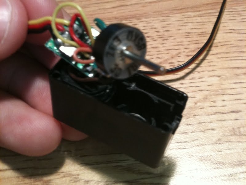
I've encountered plenty of problems with these little guys. Finally though, after buying two HS-81s, two HS-82MGs, and three HS-81 gearsets, then breaking two spline gears and a potentiometer, I have created the perfect (for my purposes) servo. Behold, the HS-82MG-360:


They said it couldn't be done. Seriously:


That's right it is spinning 360 degrees proving that impossibility is no match for being both stubborn and patient. If you're really interested in building one of these miniature torque monsters then you should see this post for details. The quick summary of how to make an HS-82MG-360 is as follows:
1. Replace the spline gear with the plastic one from an HS-81 gearset.
2. Cut out the first mechanical restrictor, found in the top of the gearcase with a pocket knife.
3. Cut out the second mechanical restrictor, found in the potentiometer. This holds the gears in place so be careful not to cut too much.
4. Cut the three wires connecting the potentiometer to the control board.
5. Solder small low-watt resistors to the loose wires keeping in mind you should:
a. Pick resistors of the same value such that their sum is the value indicated on the potentiometer. In this case, the pot read 5k and used two 3kohm resistors, so it doesn't have to be exact. I'm pretty sure the control board is just looking for a value somewhere in the designated vicinity.
b. Connect them such that the two outside wires initially from the potentiometer are individually connected to the central wire. Red-Yellow and Green-Yellow in this case.
6. Cover the exposed leads of the resistors with your choice of hot glue, heat shrink, or electrical tape.
7. Reassemble and test.

Control is handled the same way as before only this time the delay corresponds to a speed instead of a an angle. With this particular servo that's 600usec to 2400usec, 1500usec is neutral. Until next time...

Saturday, December 25, 2010

TOBL: XPWMShield V1.0

From the people who brought you Gerber Baby Food, I give you Gerber files:

Gerber minus the drill holes.

EAGLE.

I sent out XPWMShield V1.0 and the final final design hasn't changed much since the final design. Mainly, the EAGLE Drc had me make the vias a bit bigger and space out a few traces so, with those minor edits, my fingers are crossed that it will work. I learned the secret of Advanced Circuits, which is to type "Student" into the additional information box at the bottom to order Qty one. Maybe that's not a secret, but I was all ready to order the minimum four and blow ~$150. Also, Santa came through on the Weller so look out, SMD Soldering.

Monday, December 20, 2010

TOBL: Back in Business

I'm back in Massachusetts finally! To my great surprise I arrived at Logan Airport with all my luggage. Part of me was anticipating a little note from the TSA to the effect of: "Err sorry...we had to blow up your bag." Not the case though, my suitcase, featuring a square foot of aluminum, batteries, and lot's of suspect wires made it on and off the plane. So did a loaded gun though, so maybe next time I'll get more creative. Anyways, the University of Maryland was kind enough to grace us with a ~five week winter recess. It's time to exploit that and get back into this project.

Cutting out the wheel plates on the mill.

The finished pieces.

Not a perfect job on the band saw, but I took my sweet time on the mill so hopefully all the critical dimensions are in tact, which are the three outermost holes that align the gears. I'll be going into the shop as often as possible to machine the plates for the servos, the board mounts, and the rods which string all the plates together. The gears, wheels, and other little mechanical pieces are on order too.

Now, the board, or XPWMShield as it has been dubbed ("XPeeWMShield" would have been cool but I'm not that immature). It's finally done and time to send it out to Advanced Circuits! I'm pretty excited...and a little anxious since this will be my first custom board. It should be a good wireless platform for future projects. As you can tell I very much value compact-ness. This project would have been a whole mess easier to do at a bigger scale, but I like the idea of keeping things small. Final dimensions are 1.8"x3.2", which is is pretty close to the target 2"x3". I can deal with the extra length, more importantly its narrow enough to stay out of harms way when rolling.

Click to enlarge.

Fortunately I discovered that the old (HS-81) spline gears can replace those of the HS-82MG, so that means no custom gear-making. I ordered a few sets of that gearset to finish off the servos and that's all for now. I'll do my best to keep this pace through the holidays...that new soldering iron would help, Santa ;)

Tuesday, November 23, 2010

TOBL: Slowbot

So there are a couple new roadblocks in the way of TOBL, but I guess by definition engineering is solving problems. No, that's not right. "Engineering: the ultimate pursuit of laziness through hard work -Shane." Much better. After all I did throw a ton of time at a watch winder that will never do more work for me than I did to construct it.

Not a bad shot for a phone.

Anyways, the new servos are in and tested. They work very well, a substantial upgrade in torque from the HS-81s. Infact, they're better in every way EXCEPT for one kinda-super-critical detail: the spline gear does not have 360 degrees of teeth! Not sure what Hitec was thinking in that design meeting but then again I'm not their average customer. After being taken advantage of one night on GChat (and being stubborn) I think the best way to proceed is to make my own replacement gear. I don't even want to know how small pitch those gears are, but I'm going for it. Also I already opened them, and told The Internet about it so eBay probably won't take them back.

Current Gear (left), Continuous Motion Friendly Gear (right).

Unfortunately the digital readout on the mill at the shop I work out of is broken so, the aluminum plates will not be machined for a while. That gives me time to think about the rest of the frame though. There are a couple of things to consider if TOBL is going to work as planned, namely weight and rotational inertia.

Okay, nothing on this robot is going to weigh that much, but consider the following. The output torque of the servos are 38.8 oz/in, which means that 38.8/16 = 2.425lb force can be applied with a 1" moment arm. Take this times two, since there are two servos and no planned gear reduction to get a total of 4.85lb. This is about right too, taking into consideration the tipping condition where the front wheels are wedged and the entire frame must rotate around the front axle, the moment arm would be extended to the center of mass, hopefully somewhere in the vicinity of the centroid or ~1" radially.

Therefore I need to be careful about adding weight and where. The brainchild of this realization is to extend the rods supporting the gears throughout the frame, make them out of aluminum, and thin them out a bit. Then, just two small brackets to attach the electronics, and some good old zip-ties for the battery. Something like this:

Board shown in green and battery shown in blue.

Also, the heart of the software is almost complete. I started experimenting with both of the new servos at once and have so far managed to control one and both on the same signal, through the touchOSC > Processing > XBee > Arduino routing process. However, I would like the robot to turn too so right now I'm working on processing the signal to the two different servos. My lack of programming experience has definitely caught up to me but I'll figure it out. Once that's together I'll try to add in some cool buttons to the "control surface" for say spinning or trying to wheelie.

That's all for now. I'm posting mainly out of guilt knowing that the next few weeks may be busy with the holidays and finals on the horizon. The winter months should be far more productive. Happy Thanksgiving!

Monday, November 8, 2010

TOBL: Intro

The project name is TOBL and a prize goes to the first person to figure out why. You'll be hard-pressed though, it's very obscure! When I do a project, in addition to giving it a senseless name, I like to start with what I'm least comfortable with and once I'm reasonably comfortable with that, have a field day with what I do know. In the last few posts I proved to myself (maybe you too?) that I can tap my finger on a little wireless black box and touchOSC, Processing, and an Xbee/Arduino medley will know what that means. Now that I have [any] confidence in the software, it is time to have fun designing a cool robot. Here's a recap of some wired speed controlling:


So, TOBL. It'll be a 6WD robot driven by either two or four wheels at a time. This means it's pretty inefficient. However, the goal is to make this little guy freaking unstoppable! The triangular six-wheel configuration therefore is to allow it to roll over and then carry on its way (see MS Paint diagram below). For torque, I've bought a pair of Hitec HS-82MG servos, as promised. I explored the option of upgrading the gearset in the one working HS-81 and buying a new HS-81MG, but for $5 more ($45 total with shipping) I got two brand new servos with upgraded motors, controllers, metal gears, and ball bearings. Anyways, they put out 28kg/cm (whatever that means) each at 4.8V.


The drivetrain will consist of a splined pinion gear coming straight off of each drive servo to spur gears on each of the three wheels. From what I could find online it made most sense to use 48 pitch gears, which means I will have to be extremely careful when machining the plates that align the them. In the interest of cutting a little weight and getting practice with small-scale precision machining, I've made these plates as ridiculously intricate as possible. I should have a plate of 1/8" 6061 aluminum tomorrow so look for a fabrication post sometime soon. I'll do my best to stick to these designs no matter how much I'll regret it while on the mill.

Servo-side.

Wheel-side.

There will be two of these "drive units," with the servo-sides facing each other and the electronics and battery sandwiched in between. Speaking of the electronics I've decided to go all out and print a board for this little robot. It'll basically be an Arduino Nano 3.0 shield, so I think it's definitely worth while to design an accomodating platform that could be of use in further projects, and allow the expansion of this one. Perhaps once I get TOBL to move I'll start adding some sensors to the leftover pins. For now, It features a socket for an Xbee and an off-board linear 5V regulator. This may seem excessive since the Nano has an onboard regulator built-in. However, I'm a bit of a servo nut and traced four of the PWM pins to 3-pin headers specifically for servos. While I'm only using two micro servos in this project, I can imagine using more on future iterations and Nanos are not cheap to replace.

Click the schematic for bigger version.

First Schematic! The boards may not be printed for a while, kinda hoping Santa's elves will pick up the tab on this one because this project is getting quite pricey. I've already put some work into this so it shouldn't change much. I'll post a shot of the board layout and more details once I finalize and send that out. With the dimensions of the board I'll have a better idea of what the chassis will look like. I will be working hard and machining as quickly (and carefully) as possible over the next couple weeks before Thanksgiving Break!

Friday, October 1, 2010

Servo Hacking and Wireless Developments

It's been a while since my last post; I'm getting my money's worth out of school I suppose. Despite all the work I've managed to make slow and steady progress on my latest project. Here's what:

Firstly, I ordered a pair of Hitec HS-81 micro servos which truly are micro at a whopping 1.2"x0.47"x1.2". Naturally I had to pry them open and have a look around the insides. The idea is to convert them to continuous motion so they can eventually drive some gears. Here were the obstacles in doing that:

Little plastic mechanical stop in the gear case.

No Problem.

Potentiometer.

Tricked the servo with a couple resistors, no sweat.*

*Except I chipped a tooth.

Now, because these servos are so small the shaft of the potentiometer is actually used to align some of the gears and I couldn't just get rid of the pot altogether. Instead I filled it with hot glue so that it couldn't rotate (not sure why since I cut the wires from it), put it back in place, and reconnected it to the gears. Unfortunately, the end of the shaft is keyed to fit into the spline gear. I cut out the excess material in the gear to assure that the shaft could rotate freely, but at this small scale that is not easy and when I went to test it the gear still caught on the pot, locked up, and broke a tooth.

Lesson learned: drill out the gear the right way, not with a pocket knife. Also I'm going to order these servos' big brother the Hitec HS-82MG, for the final product which features metal gears for about $4 more.

With one servo left I could still test out the XBee radios. The basic concept of this project is to control an Arduino with an iPhone over wifi, and then over radio with XBees. In the previous post I determined I could make it from A to B, so now it was time to test from B to C. To do this I got a breakout board and an explorer board and crammed them onto a breadboard like so:

Nothing too tricky here other than a voltage divider circuit with a few resistors to bring down the Arduino's 5V output to the 3.3V that the XBee module runs on (Thanks Shane!). It's also important to note that thou shalt remove the radio while programming. I don't exactly know why this is yet, but it's going to throw an uploading error at you if you don't.


It works! In fact, I also got A to B to C working, but couldn't record it since I use my iPhone camera for video. Maybe I could have figured something out...with mirrors? For now you'll have to take my word that it works. It was actually surprising how easy these radios are to implement. You have to make sure the baud rate of the Arduino is the same as the XBees, but that's the only change I made to the existing test code. Next step is to refine this crazy control sequence and start speed control testing, hopefully with some working continuous motion servos.

Friday, September 3, 2010

New Project Trailer

I picked up an iPhone 3Gs a week ago and have already taught it some tricks courtesy of the wonderful touchOSC app. Accompanied by the OSC editor freeware, this program allows you to create your own GUI for the iPhone/iPad (I think they have an Android version too?) for controlling all your musical or embedded electronics projects. Yes, it's $4.99 but in my opinion it's well worth the price of admission. In fact, it's the only app I have justified paying for so far.

After playing with my toys for a bit I finally found reason enough to invest in some very small servos to join the Arduino Nano 3.0 and XBees sitting on my desk. And so begins the next project:


No sound I guess...

There is a great guide on SparkFun for syncing OSC over wifi, to Processing, to an Arduino via USB. After tweaking the code - originally intended to control an LED - a little bit the iPhone can control ardWINDo's servo. I won't spill the details now, but I will say that my next project will be mobile. Watch-winder's are cool and all but only watches can ride them...